

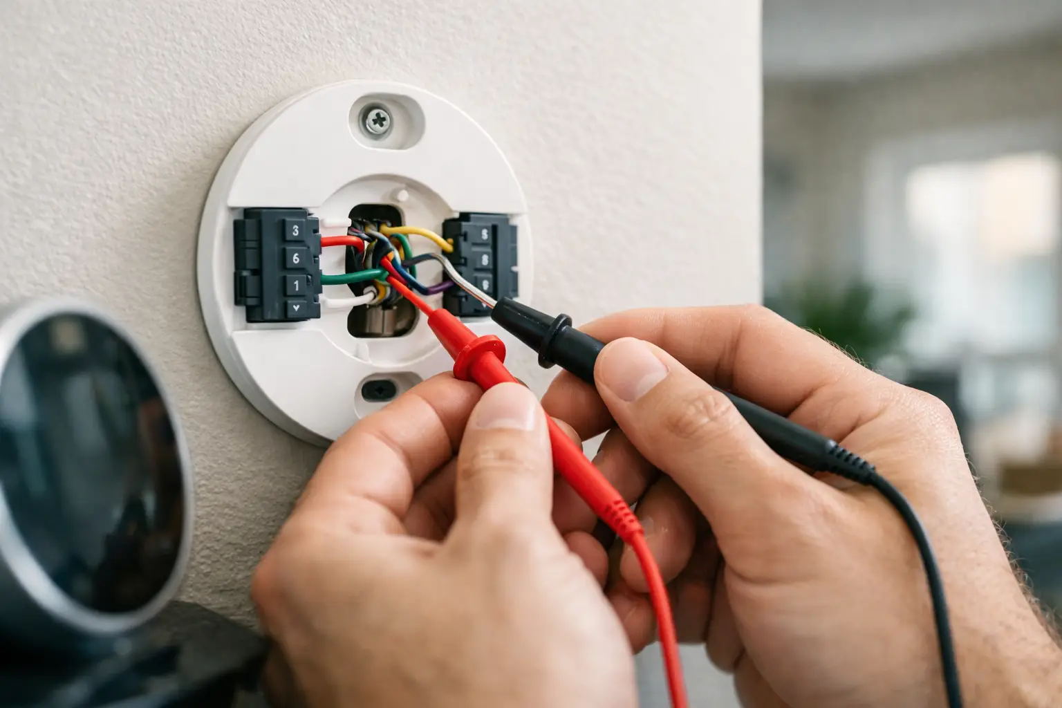
A thermostat that goes blank, will not call for cooling, or runs the fan without heating or AC does not automatically mean the thermostat has failed. A loose wire, blown low-voltage fuse, damaged cable, or issue inside the equipment can create the same symptoms. Knowing how to test thermostat wiring can help you narrow down the problem without guessing or replacing parts that may still be good.
Most home HVAC thermostats use 24-volt control wiring. That voltage is lower than household power, but the air handler, furnace, heat pump, and outdoor unit contain 120- and 240-volt circuits. Treat the thermostat as a diagnostic starting point, not a place to take shortcuts. If you are uncomfortable opening equipment panels or using a multimeter, stop and call a qualified HVAC technician.
Start With Safety and the Right Tools
Before touching any thermostat wire, turn off power to the HVAC equipment at its dedicated breaker or service switch. Do not rely on the thermostat’s Off setting. It stops a call for heating or cooling, but it does not necessarily remove power from the control circuit.
You will need a small screwdriver, a flashlight, a phone to take reference photos, and a multimeter that can read AC voltage and continuity. Wire labels or masking tape are also useful if a wire has come loose. Thermostat terminals are small, and moving one wire to the wrong location can create a new problem.
There is one major exception to the usual 24-volt setup: line-voltage thermostats used with some electric baseboard heaters, wall heaters, and commercial equipment. Those systems can carry 120 or 240 volts at the thermostat. Do not use the low-voltage testing steps below on a line-voltage thermostat. If the wiring is thicker than typical thermostat cable or enters the thermostat through conduit, have it checked professionally.
Identify the Thermostat Wires Before Testing
Remove the thermostat face from its wall plate. On many models, it pulls straight off. Others have a small release tab. Take a clear photo before disconnecting anything, especially if the wire colors do not match standard conventions.
The terminal letters matter more than wire color. In a typical conventional furnace and air conditioner system, the terminals may include R for 24-volt power, C for common, Y for cooling, G for the indoor blower, and W for heat. Heat pump systems commonly use Y, G, R, C, O/B for the reversing valve, and AUX or W2 for auxiliary heat.
A red wire is often connected to R, yellow to Y, green to G, white to W, and blue or black to C. “Often” is not the same as “always.” Installers may use whatever conductor is available, particularly after a repair or thermostat upgrade. Follow the terminal labels, not assumptions about color.
If you see separate Rc and Rh terminals, do not remove a factory-installed jumper unless your system has separate cooling and heating transformers. Most single-system residential setups use one R power source. A missing or incorrectly placed jumper can make part of the system appear dead.
How to Test Thermostat Wiring With a Multimeter
The first useful test checks whether the thermostat is receiving 24-volt power. Restore power to the HVAC equipment, keep your hands clear of equipment panels, and set the multimeter to AC volts. Select a range that can read roughly 24 to 30 volts.
At the thermostat wall plate, place one meter probe on the R or Rc terminal and the other on the C terminal. A healthy control circuit usually reads around 24 to 28 VAC. Readings vary somewhat by transformer and load, so a number slightly outside that range is not automatically a failure. No voltage, however, points to a power-side issue rather than a thermostat setting.
If you do not have a C wire connected at the thermostat, test R to G, R to Y, or R to W with the thermostat calling for that function. This can provide a clue, but it is less definitive than an R-to-C test. Modern smart thermostats may require a true C connection or a properly installed power adapter. A thermostat that loses power repeatedly may have a wiring issue, but it can also be responding to a clogged condensate drain safety switch, a blown fuse, or an equipment fault.
When R-to-C voltage is absent, check the breaker, the furnace or air handler service switch, the equipment door panel, and the low-voltage fuse on the control board. Many systems use a small 3- or 5-amp automotive-style fuse. If it has blown, do not simply replace it and hope for the best. A blown fuse often means a short in the thermostat cable, outdoor-unit wire, contactor coil, or another control component.
Test Whether the Thermostat Is Sending a Call
If R-to-C voltage is present, set the thermostat to Cool and lower the set point several degrees below room temperature. Depending on the system and thermostat, there may be a short delay before cooling starts. At the wall plate, test between Y and C. When cooling is being called, you should generally see approximately 24 VAC.
For heating, switch to Heat and raise the set point above room temperature. Test W to C on a conventional gas furnace or heat strip system. On a heat pump, the correct terminal may be AUX, W2, or another terminal based on the equipment configuration. The meter should show approximately 24 VAC when that specific call is active.
For a fan-only test, set the thermostat fan to On and measure G to C. If voltage appears at the correct terminal but the system does not respond, the thermostat may be doing its job. The problem could be at the air handler, furnace control board, safety circuit, outdoor unit, or another component farther down the line.
This is why accurate diagnosis matters. A thermostat can look guilty because it is the part you interact with, while the actual failure is a float switch, a broken low-voltage wire outside, a failed transformer, or a control board problem.
Check for Loose, Broken, or Shorted Wires
Turn power back off before testing wire continuity or handling bare conductors. At the thermostat, inspect each wire for loose terminal screws, corrosion, cracked insulation, or conductors that are barely making contact. Only a small amount of copper should be exposed. Too much bare wire can touch a neighboring terminal and short the control circuit.
Thermostat cable is especially vulnerable where it passes through a crawlspace, attic, wall cavity, or exterior wall near the outdoor unit. Rodents, moisture, nails, and weed trimmers can damage it. In the Charlotte area, moisture around air handlers and condensate drains can also contribute to corrosion or safety-switch problems that are mistaken for wiring failures.
A true continuity test requires disconnecting the wire at both ends, usually at the thermostat and at the furnace, air handler, or control board. With power off, set the meter to continuity or resistance. Connect the two ends of the same conductor using a temporary jumper at one end, then test for continuity at the other. No continuity suggests a broken conductor. Continuity between two wires that should be separate may indicate a short.
This test is reliable, but accessing the equipment-side connections can be difficult. If you cannot confidently identify terminals or safely remove panels, it is better to stop there. A technician can trace the circuit without risking damage to the transformer or control board.
Do Not Bypass Wires as a Permanent Fix
Some online advice recommends touching R to Y, G, or W to “jump” the thermostat. Technicians may use controlled jumper tests during diagnosis, but it is easy to short terminals, defeat safety controls, or misread the result. It also does not tell you why the system failed.
Avoid bypassing condensate switches, pressure switches, door switches, or other safety devices. Those components are designed to stop operation when water, airflow, combustion, or electrical conditions are unsafe. The honest repair is to find the cause of the safety shutdown, not force the system to run around it.
When It Is Time to Call for HVAC Service
Call for service if the low-voltage fuse blows again, the thermostat has no R-to-C voltage, the wiring is damaged inside a wall, or the system receives a call but will not start. The same applies if you smell burning, see melted insulation, hear buzzing from the transformer, or have a heat pump that is not configured correctly after a thermostat replacement.
For homeowners and commercial property operators, the practical goal is not to prove the thermostat is bad. It is to identify whether the thermostat, wiring, or HVAC equipment is actually responsible before money is spent on the wrong repair. DDL Services approaches these issues from the diagnostic side first: find the failed part, explain what the readings mean, and recommend only the repair the system needs.
A quick voltage check can provide useful answers, but a stable, safe HVAC system depends on the entire control circuit working together. If the test points beyond the thermostat, let the next step be a proper diagnosis rather than a replacement guess.